About Me

My photo
Starting my journey into the world of Microcontrollers, electronics and programming, a bit late in life (but your never to old to learn).

Tuesday 26 April 2016

Raspberry Pi CamJam EduKit 2 - Sensors - Part 1 Worksheets 1 and 2

CamJam EduKit 2 kit contents
Kit Contents:

  • 1 x Breadboard
  • 1 x Immersible temperature Sensor
  • 1 x PIR Sensor
  • 1 x LDR
  • 1 x Active Buzzer
  • 1 x Red 10mm LED
  • 1 x Blue 10mm LED
  • 1 x 4.7K Resistor
  • 2 x 330 Resistor
  • 10 x M/F Jumper Wires (Red)
  • 4 x M/M Jumper Wires (Green)

Worksheet 1:

This worksheet covers setting up the Raspberry Pi, so you can do all the worksheets. This time also had to add a line to the boot/config.txt file, so you can use the Immersible temperature Sensor.

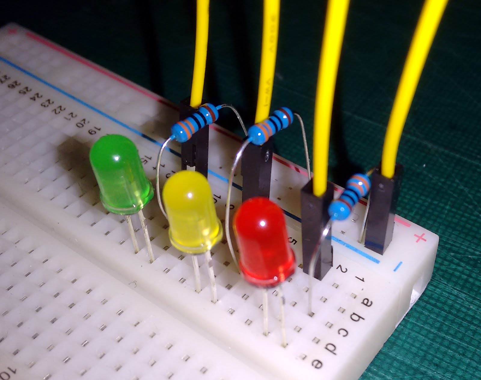
Worksheet 2: LEDBuzz


Diagram and what it actually looked like.


LEDBuzz; this programme turns the LEDs and the buzzer on for one second, and prints 'Lights and sound on' on to the screen,  then turns LEDs and Buzzer off, then prints 'Lights and sound off' onto screen.


Saturday 23 April 2016

Raspberry Pi CamJam EduKit 1 Part 3 Worksheets 6 and 7

Worksheets 6 and 7 Wiring:


Worksheet 6:

This programme just uses the buzzer to sound out SOS, and then there are two challenges (which I am working on).


Worksheet 7:

Uses LEDs, Button and Buzzer. It copies how traffic lights work;
  • Green light for traffic
  • Press button (waits 10 seconds)
  • Amber
  • Red and buzzer
  • Amber flashes
  • then back to Green


Raspberry Pi CamJam EduKit 1 Part 2 Worksheet 5

Worksheet 5: Push Button for Physical Input


The code from the worksheet uses the button and not the LEDs, you get a message on the screen when you press the button.

Thursday 21 April 2016

Raspberry Pi CamJam EduKit 1 Part 1 Worksheets 1 to 4

CamJam EduKit 1 kit contents
LINKS:
Cambridge Raspberry Jam: http://camjam.me/
Can be purchased from (in UK): https://thepihut.com/collections/camjam-edukit/products/camjam-edukit?variant=771534813
Code and Worksheets: https://github.com/CamJam-EduKit/EduKit1

Kit Contents:

1 x Breadboard
1 x Buzzer
1 x Red LED, 1 x Yellow LED, 1 x Green LED
1 x Push Button
3 x 330ohm Resistor
1 x 4.7k ohm Resistor
7 x Male/Female Jump Wires (All Yellow)
2 x Male/Male Jump Wires (Both Green)

Worksheet One:

The first worksheet takes you through getting things set up on your Raspberry Pi, everything is very well explained, in easy to follow steps.

Worksheet Two: Starting to actually build a circuit

Even though I have ones of different colour Jump wires, I'm going to stick with the items that came with the kit.

The first programme switches all three LEDs on, the second programme switches them all off. Learnt importing Library, define which pins are going to be used and what they are going to be used for, and switching the LEDs on and off.
Left: On - Right: Off programmes

Worksheet 3

Still using the same wiring this worksheet teaches how to get the LEDs to blink with first by adding the first two programs together and repeating them, then introduces the LOOP.

Left: Blink Twice - Right: Blink Forever programmes
One line of code I have got to try and remember, as it could come in very useful is: GPIO.cleanup() as this makes sure the GPIO pins are all off/LOW.

Worksheet 4

This worksheet is still using the same wiring, but now the programme introduces user input. You choose which LED to blink, and how many times it will blink.
4 -Code

Monday 18 April 2016

Potentiometer Part 2

Arduino Examples

Analog Read Serial and Read Analog Voltage

Reads an analog input on pin 0, prints the result to the serial monitor

CODE FROM ARDUINO.CC 

 Both of these examples use the same wiring and component (10k ohm Potentiometer), but the programs are different. Both use the UNO R3 Boards analog-to-digital converter.


I had trouble getting the Raspberry Pi Zero to run these two sketches, they did run but the read out was very slow and not showing the results equal to where the knob was on the potentiometer. The Raspberry Pi 3 was able to run these okay.

Analog Read Serial:

In this program the  analog-to-digital converter shows the resistance of the Potentiometer in a value between 0 to 1023 in the Serial Monitor (which you get by clicking on the magnifier on the upper right side of the Arduino IDE).
/*
  AnalogReadSerial
  Reads an analog input on pin 0, prints the result to the serial monitor.
  Graphical representation is available using serial plotter
  (Tools > Serial Plotter menu)
  Attach the center pin of a potentiometer to pin A0,
  and the outside pins to +5V and ground.

  This example code is in the public domain.
*/

// the setup routine runs once when you press reset:
void setup() {
  // initialize serial communication at 9600 bits per second:
  Serial.begin(9600);
}

// the loop routine runs over and over again forever:
void loop() {
  // read the input on analog pin 0:
  int sensorValue = analogRead(A0);
  // print out the value you read:
  Serial.println(sensorValue);
  delay(1);        // delay in between reads for stability
}


Analog Read Serial Output

Read Analog Voltage:

This time the analog-to-digital converter shows the resistance of the Potentiometer in volts from 0 to 5 volts in the Serial Monitor.
 
/*
  ReadAnalogVoltage
  Reads an analog input on pin 0, converts it to voltage, 
  and prints the result to the serial monitor.
  Graphical representation is available using serial plotter
  (Tools > Serial Plotter menu)
  Attach the center pin of a potentiometer to pin A0,
  and the outside pins to +5V and ground.

  This example code is in the public domain.
*/

// the setup routine runs once when you press reset:
void setup() {
  // initialize serial communication at 9600 bits per second:
  Serial.begin(9600);
}

// the loop routine runs over and over again forever:
void loop() {
  // read the input on analog pin 0:
  int sensorValue = analogRead(A0);
  // Convert the analog reading (which goes from 0 - 1023) to a voltage (0 - 5V):
  float voltage = sensorValue * (5.0 / 1023.0);
  // print out the value you read:
  Serial.println(voltage);
}


Read Analog Voltage Output

I think I will be coming back to the Potentiometer, when I have more understand of programming, and electronics.

Friday 15 April 2016

Raspberry Pi CamJam Education Kits

Have received the three CamJam Education kits today from The Pi Hut:


Link to page: https://thepihut.com/collections/camjam-edukit

Link to CamJam Web site: http://camjam.me/?page_id=618

Potentiometer Part 1

Potentiometer (a three terminal resistor), a nob that provides variable resistance.

Second example from Sparkfun varies the speed of an LED blinking, and from the Arduino IDE Basics example Read Analog Voltage.

First the Sparkfun example:

Wiring and items used diagram

What it really looks like


The video shows what the programme and the components actually do, as you turn the nob on the Potentiometer it varies the speed of the LED blinking. Cannot say I fully understand the programme, but do get the gist of what each line does.


Thursday 14 April 2016

Arduino - Blink LED

Thankfully the first example for the Arduino is easy to understand, both the wiring and the code. First I just tried the example using the LED on the UNO R3, then I looked on the web for more detail and examples.

Next I put an LED into the pins (positive in pin 13 and negative into the GND pin next to 13).
 and then I read if you want the LED to last you need to use a resistor, so I then find 2 different ways of wiring up a breadboard for the Blink example with a resistor.


I liked the explanation and diagrams from Sparkfun for their SIK Experiment Guide for Arduino - V3.2.

Link:  https://learn.sparkfun.com/tutorials/sik-experiment-guide-for-arduino---v32

I do not have the kit (might get it), so for now cannot do all the examples (yet). But it looks like a great site for beginners.

Starting a journey of learning and fun

This is going to be more a diary of what I have done and learnt sort of blog, as it is nearly all new to me, especially the electronics and programming.

I got a Raspberry Pi Model B and a Model A a few years ago, and they ended up in a cupboard. Now they have been dusted down and been joined by a Raspberry Pi Zero (I got free with issue 40 of The MagPi), and a Raspberry Pi 3 Model B+, so I got to start learning how to use them.

The Arduino is something that has looked interesting to me for a little while, as I am interested in how things are made and work, but my lack of knowledge about electronics has always put me off. I took the plunge and bought an Arduino UNO R3 copy, as it is cheaper if I do anything drastically wrong at the beginning. When I get a bit more confident one will buy an official board.

Raspberry Pi Zero
At the moment I have set up the Raspberry Pi Zero for programming the UNO R3, I've installed the Arduino.cc IDE and Fritzing onto it. The reason for choosing the Raspberry Pi Zero is that it comes with no GPIO pins.


UNO R3